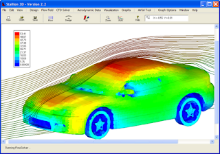
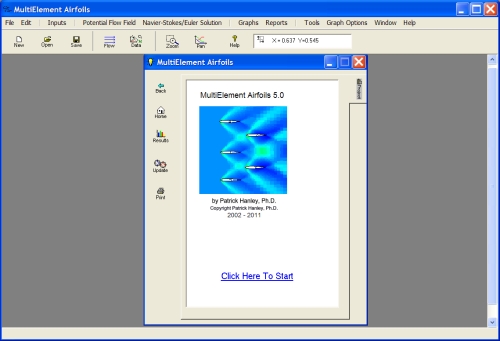
Tuesday, April 24, 2012

Setup Complete Aircraft for Analysis in About One Minute

Often it is necessary to analyze a complete airplane to determine loads, moments and stability (with and without stores, gears and external tanks) for various flight configurations.

Stallion 3D is a unique MS Windows software that simplifies this task by importing a CAD model that represents the geometry of interest and then automatically perform the necessary computing to generate the aerodynamics information.

Stallion 3D uses an novel formulation of the immersed boundary method, IBM, (based on a 3D Cartesian grid) to automatically detect immersed geometries and perform grid refinement at the boundaries.  Hanley's original ghost-cells based boundary scheme is automatic and can even work with near-zero-thickness surfaces to model sails and other aerodynamic structures.

The following video shows how to input the full 3D aircraft for analysis in Stallion 3D. Given a .stl (from NASA VSP, for example) the setup time is about one minute. Please click the following link to view the video:


More information about Stallion 3D can be found at: http://www.hanleyinnovations.com/stallion3d.html

Do not hesitate to contact us at (352) 240-3658 for more information.

BTW, here are a few recent pictures from Stallion 3D.  In some images, the geometries are from TurboSquid.com. Other geometries were created using Stallion's built-in wing editor.

Meteor at Mach 10.  Picture shows the temperature field.

Cartesian grid for joined-wing (box wing) model.

Sailboat simulation demostrating the ability to analyze thin surfaces.

Building and trees in the wind (steady flow).


Thanks for reading and best regards.

Wednesday, April 11, 2012

NASA Vehicle Sketch Pad

NASA's  Vehicle Sketch Pad (VSP) was released in January 2012 as an open source program.  VSP is an easy-to-use CAD software package dedicated to the rapid design of 3-dimensional solid models of airplanes, UAVs and other aircraft types.  More information about VSP (OpenVSP) and links to download a free copy can be found at the following page: http://www.openvsp.org.  The following video demonstrates the ease of use of VSP:


Additional tutorial information can be found at the following link:  http://www.openvsp.org/vid_tutorial.html

VSP exports to a variety of formats including .stl files.  This allows you to export your solid model for additive manufacturing or analysis in Stallion 3D and  other CAE programs:


Vehicle Sketch Pad and Stallion 3D (or similar program) are ideal tools for rapid aerodynamics conceptual design and analysis of aircraft.  Stallion 3D  can import the aircraft geometry in a single step using the .STL import function under the Design menu:

It's easy to import a STL file from VSP into Stallion 3D

Once the aircraft is imported in Stallion 3D, it will generate a grid and analyze the aircraft with a single click.  The user can also select the speed and other parameter for the aircraft.  In the following case for the Boeing 747-400, the speed is 290 meters/second and the angle of attack is 5 degrees:

This analysis shows the surface pressure and the Cp at various span locations.

Once you design and analyze one vehicle in VSP and Stallion 3D, it is hard to stop.  The following pictures show the pressure on the surface of two of the other complete aircraft that comes with VSP:

Pressure on surface of Cirrus aircraft included in VSP.

Pressure on the surface of  Cessna aircraft included in VSP

In short, NASA Vehicle Sketch Pad is a fun program to download and design aircraft.  It is even more fun to use Stallion 3D to analyze the aircraft and test the design in a digital wind tunnel.

More information can be found at http://www.hanleyinnovations.com/stallion3d.html
What is your favorite tools for rapid design and analysis?

Do not hesitate to email or call me at (352) 240-3658 if you have any questions. Thanks for reading and best wishes.  Patrick.

Friday, March 9, 2012

Replacing Paper: Future of Back-of-the-Envelope Analysis

Will the computer replace paper for rapid conceptual design & analysis?

Back in the day, if someone asked you a "quick" question or you had a brilliant idea (perhaps one that would change the world), the first thing to do is to move objects around your desk until you find a pencil and a piece of paper (the thought is fleeting and you will not remember if not immediately committed to paper).

Next, you feverishly sketch drawings and write down equations until you realize "ah, this will work! (or not)". This activity is the beginning of the conceptual analysis process. If your idea is really-really good, the piece of paper that you will randomly find is an envelope (perhaps from a bill or unsolicited advertisement).

The reason for the back-of-the-envelope calculation is to jot down your ideas using a medium that is totally familiar (and responsive) before you forget (or misinterpret) the volatile thought.

No matter how well you can draw or how quickly you can perform algebra, the back-of-the-envelope lacks robust computation power. It is often tucked into an ajar desk draw or between the pages of your favourite fluid dynamics text until you can find more time to complete the thought.

However, while we were sharpening our pencils, someone was trying to "improve" the back of the envelope process. The video below shows how a computer can be used to sketch drawings on a surface and the "paper" will actually solve the problem.


This can work for aerodynamics as well. The video below shows Hanley Innovations' MultiElement Airfoils as a conceptual analysis tool for deciding the position and orientation of a group of airfoils. The software can generate the lift, drag and moments for any configuration. It can save the configurations and export the shapes and positions to a .dxf file. More information can be found at http://www.hanleyinnovations.com/mefoil.html.


Paper is indeed changing. The video below shows Autodesk ForceEffect on the iPad. The program allows drawing on the screen to solve statics problem using free body diagrams.


Do you think that the computer will replace the back of the envelope?

For more information about Hanley Innovations' interactive aerodynamics analysis software, please visit: http://www.hanleyinnovations.com/

Thanks for reading, Patrick.

Tuesday, February 14, 2012

Top 10 Reasons to Analyze Your Airfoil

Here are my top ten reasons (no particular order) to analyze your airfoil shape.  

10.  Bricks make terrible airfoil shapes.  Circular shapes do not provide any lift (unless they are spinning).  The airfoil shape makes a difference even if it is not the dominant parameter.

Brick analysis by MultiElemnet Airfoils 5.0: see http://www.hanleyinnovations.com/mefoil.html

9. You can perform airfoil analysis free of cost using XFoil (albeit you cannot analyze the above bricks with this program).  Price is no excuse not to analyze your airfoil.  See: http://web.mit.edu/drela/Public/web/xfoil/

8.  You are forced to learn about Reynolds number and how it can ruin the looks or your airplane (but possibly save your life).  Investigating the behavior of the airfoil shape as a function of Reynolds number can improve the safety of your designs.

7.   Some shapes provide better lift than others at the same angle of attack and speed.  Find out which ones can make or break your project.

Lift Coefficient vs. Angle of Attack. Computed with VisualFoil 5.0

6. Some shapes can provide the required lift (desired loading characteristics) without the increased expense of drag.  This helps you to win races, save fuel and have a good feeling about your design.

Lift Coefficient vs. Drag Coefficient. Computed with VisualFoil 5.0

5.  Some good looking airfoils turn out to provide bad stall behavior. Use analysis to determine the stall angle and maximum lift coefficient of your cross sectional shape.

Lift Coefficient vs. Angle of Attack (showing maximum lift). Computed with VisualFoil 5.0

4.  The moment of truth.   Some airfoils (especially those that provide high lift) often demand in return a huge horizontal stabilizer for longitudinal stability.    You do not want your design to have a high sink rate due to tail drag.

Moment Coefficient vs. Angle of Attack. Computed with VisualFoil 5.0
3.  Speed can slow you down.  It is necessary to know the transonic behavior and the drag divergence Mach number of your airfoil if you design propellers, turbines and jet airplanes.
Drag divergence of an airfoil.  Analysis by VisualFoil Plus:  http://www.hanleyinnovations.com/air_16.html
 
2.  Airfoil analysis inspires you to find more about airfoil characteristics and terms.  You will learn about reflexed airfoils, laminar flow airfoils, high lift airfoils, cambered shapes, split flaps, slotted flaps ....... and how they can be beneficial to your design and project.


1.  VisualFoil 5.0 is a powerful and user-friendly tool for airfoil analysis and design.  It has a built-in library of 1000s of airfoils including the NACA 4, 5 & 6-digit shapes.  Users can also enter custom airfoils as coordinates or .dxf files (line & arc entities).   Hanley Innovations can provide help with setting up your airfoil project, interpretation of the results and provide recommendations.  There is no reason not to produce a successful design.
More information about airfoil analysis and VisualFoil can be found at Hanley Innovations.  Please visit http://www.hanleyinnovations.com/

What are your reasons for airfoil or CFD analysis?

Thanks for reading.

Friday, February 3, 2012

Car Aerodynamics Calculations

Often it is necessary to quickly determine the aerodynamics characteristics of a production vehicle or a new prototype before further testing or construction can move forward.

Hanley Innovations developed Stallion 3D for rapid aerodynamics analysis of three-dimensional solid models.   This software is a quick and inexpensive option to perform aerodynamic conceptual analysis on a 3-dimensional CAD model without the time-consuming ritual of grid generation.  The analysis can be performed on your desktop computer or laptop. 

The following steps can be followed to determine the lift and drag on a road vehicle.
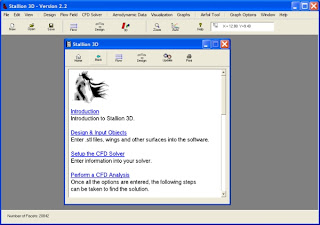
Stallion 3D Main Window
To start the analysis, click on the design menu and select the Import or Edit .STL file option.  This will invoke the .stl file editor show below.   The editor allows you to read in files in the ASCII format and then provide a quick preview of the input.   Stallion 3D can analyze files that are water-tight.  If your file has holes, you might be able to repair them with the free utility called Netfabb-Studio Basic. Netfabb studio can also convert files from a variety of formats to the .stl format.
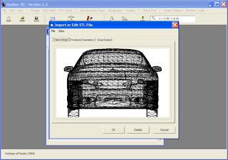
A car from Turbosquid.com as seen in Stallion 3D.
The .stl input box also allow you to rotate and translate the part.  This allows you to point the leading edge of the model (longitudinal direction) along the x-axis and the lateral direction along the y-axis.
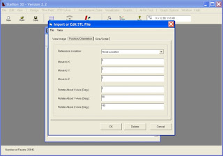

The .stl dialog box can be used to orient the model.

Before exiting the .stl import box, you can also explore the options to scale the model and set the correct dimensions.  The default in Stallion 3D is meters, however, you can select inches, feet and cm.
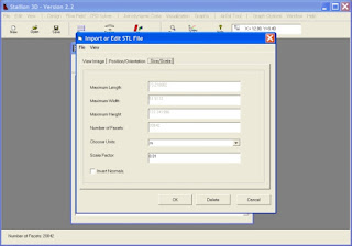
Scale and dimension the solid model.
Once the part has been imported into Stallion 3D, it can be view in wire frame mode in the Design Editor.  This screen can also be used to add more components (such as wings) to the model.
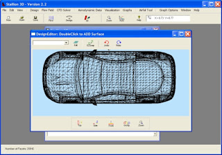
The design editor window can be used to add wings and other components to the model.
The next step is to analyze the model.  Stallion 3D performs a 3-dimensional CFD analysis on an ordinary PC running MS Windows.  The user can choose the model size and settings by clicking the CFD Solver menu followed by the Setup CFD option.   In the first tab, the user can select the CFD problem size (number of nodes) and layout.   The options are for a quick run (less accurate) or a moderately sized problem (more accurate).  In this problem, I choose a Small Size ( less than 240,000) nodes. 
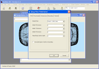
The user can choose the problem size.  A quick run is helpful to test the setup.
The next option is to choose the flow domain dimensions and location.  The flow domain is a big cube. I recommend that the length of the flow domain is about 10 times the maximum length of the part.   This allows quicker convergence and better accuracy for the radiation boundary conditions. 
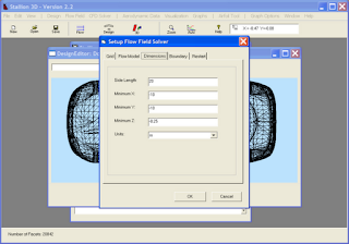
Set the flow domain dimensions to simulate the physics and facilitate convergence.
For the car problem, I select the lower z-dimension to coincide with the ground and then make the ground a reflection plane (instead of a radiating boundary).  This will simulate the hard road.
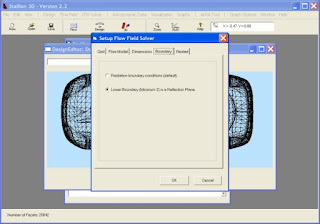
Set the lower boundary as reflective (instead of radiative) to simulate the road.
The next step in the solution is to set the flow speed and reference areas and lengths for the lift, drag and moment computations.  

Finally, simply click the CFD Solver menu and select Generate Grid/Solve flow.  The program will automatically generate the grid and launch the flow solver.  For this specific problem, the grid generation took about 20 - 30 minutes on my laptop.  The algorithm generated 132,833 nodes.


Once the grid was generated, the flow solver started to solve the 3-dimensional compressible Euler equations (with the low speed flow option).  The solver computes the lift, moments and pressure drag for the 3-dimensional configuration with good accuracy.  Stallion 3D can also solve the 3-D Navier-Stokes equations for the same configuration.
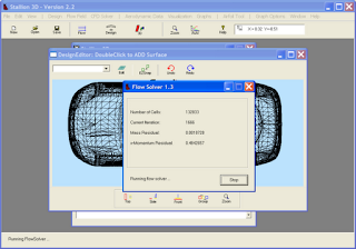
The flow solver updates 132,833 nodes every iteration using a 4-stage Runge-Kutta method.
 The solution converges in less than 2 hours for this problem on my laptop computer.   The windows below shows the pressure computed on the surface of the car.  This is obtained by clicking on the Visualization menu and selecting the View Solution option.
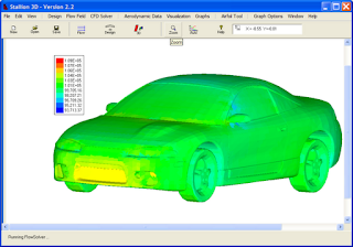
Pressure on the surface of the car.
 The speed near the surface of the car is a useful design parameter for drag reduction and flow visualization.   Stallion 3D allows the user to see the pressure, Mach number, velocity and temperature on the surface of the part.
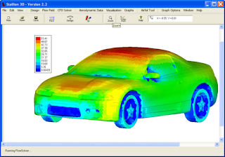
Velocity on the surface of the car.
 Another technique to assess the quality of the solution is to look at the streamlines and flow at the ground plane.  The following  graphs show these two images.
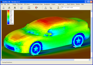
Velocity at the ground plane.

Flow streamlines.
 Stallion 3D computes the overall lift, drag and moments acting on the vehicle.  These numbers can be used as design parameters to improve and determine the performance of the vehicle.   The moments can also be used to determine stability with subsequent computations.
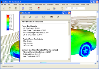
Computed lift, drag and moment coefficients based on vehicle frontal area.
Note, the .stl file must be in very good shape for good computation of the forces and moments.  It must not have multiple facets (in the same location) and inverted facets.  If this is the case, the user can approximate the forces on the Cartesian-front (an approximate representative of the car).  This method, however, is not valid for downforce calculation.  A good .stl file is required for downforce calculation when the lower boundary is used as a solid wall.

More information about Stallion 3D can be found at http://www.hanleyinnovations.com/

Thanks for reading.

Wednesday, November 23, 2011

Can a Turkey Escape Thanksgiving?

When in danger, it is a well known fact that turkeys can muster up very high flight speeds. Some legends have it that they can fly at supersonic speeds. 


An often overlooked fact is turkeys are extremely adept at aerodynamics and CFD analysis. They never attempt an unfamiliar regime of flight without careful analysis.

So when told about Thanksgiving, a young bird was not at all happy about its prospects.  It decided to find a way to beat the system.  "Perhaps", it thought,  "I can use my supersonic flight capabilities to escape the humans."

A quick google search revealed that humans have jet aircraft that are also capable of supersonic flight.  What are the consequences (if any) of  supersonic flight and out running a jet?

Stallion 3D Mach number analysis at M = 1.5.

Using it's laptop PC and Stallion 3D, the turkey was able to perform a careful CFD analysis within a few minutes.  A variable of concern was the temperature.

Simulation of Turkey & Jet.  Notice Temperatures....

At Mach 1.5 (a reasonable speed), the analysis showed temperatures of 466 degree K or 380 degrees Fahrenheit on most of the bird's body.


Another quick google search showed that Martha Stewart recommends that you cook your bird at 325 F.

"Hmm.... ", the turkey thought, "Can a turkey ever out run Thanksgiving?" 

"Yes!!!" exclaimed the turkey, answering its own questions, as it applied a gell-like substance (resembling cranberry sauce but with a negligibe coefficient of thermal diffusivity) to the areas indicated by red on the temeprature charts (above picture).


Happy Thanksgiving from Hanley Innovations.
http://www.hanleyinnovations.com/stallion3d.html

Friday, October 14, 2011

Analyzing "Difficult" Airfoils

Using a computer program to analyze the cross section (airfoil) of a wing, keel, sail combination or race car spoiler gives the design engineer valuable insight into the behavior and efficiency of the device.  Furthermore, airfoil analysis provides a cost effective and quick first step in the conceptual design of the product.   However, using conventional airfoil analysis tools (often based on panel methods) cannot handle a number of "difficult" shapes that are of interest to the modern design engineer.   For example, panel methods have difficulty with truncated or blunt airfoils, airfoils with gurney flaps or wicker bills (often used on high end race cars), ground effect,  thin airfoils (for modeling yacht sails) and airfoils at high angles of attack (for modeling wind energy devices).


Multi-Element wing section in ground effect computed using MultiElement Airfoils.

Computational fluid dynamics (CFD)  based on the Euler or Navier-Stokes equations provides solutions where panel methods fail.  However, even in two-dimensions, general CFD methods can prove to be costly and time-consuming due to the grid generation process for complex geometries.

MultiElement Airfoils 5.0 provides a unique solution based on Euler/Navier-Stokes equations and automatic Cartesian grid generation method.  The software is a turn-key approach to airfoils analysis (with a library of built-in airfoils and the ability to read-in DXF shapes) where solving a challenging system of multiple cross sectional shapes is as easy as analysing a single conventional airfoil.

MultiElement Airfoils is an Euler/Navier-Stokes solver based on
an automatic Cartesian grid method.

A user can enter the shape from the library of airfoils, a custom shape from a file containing the airfoil ordinates or a .dxf file.  In this case, a blunt airfoil shape is shown in the picture below.

Blunt airfoil geometry in MultiElement Airfoils.

The analysis starts by automatically generating a Cartesian grid using the program's menu system.

Automatic Cartesian grid adapts to the emersed boundary.

Next, the user can choose either an Euler equations solution or Navier-Stokes solution.  The picture below shows the Euler equations solution coupled with a boundary layer solver.  The program displays pressure, velocity ratio (seen below), Mach number, Temperature and density.

Flow velocity ratio with streamlines.

Airfoils with Gurney flaps (wicker bills) used in the racing industry can also be easily and accurately analyzed with MultiElement Airfoils 5.0.

Gurney flap grid in MultiElement Airfoils.

The Navier-Stokes solution is chosen for this analysis (the Euler solution was also obtained for comparison).  The pressure field is shown in the below picture.

Gurney flap solution showing pressure and streamlines.

The following picture shows the flow close to the gurney flap.  It features a double separation region downstream of the flap.  On the left side of the screen, a comparison is made between the surface pressure coefficient of the main airfoil and the flap computed using the Euler equations and the Navier-Stokes equations methods.

Streamlines near the trailing edge as computed in MultiElement Airfoils

Another application of MultiElement Airfoils is in analyzing thin airfoil shapes.  This is useful for the design and analysis of the propulsion system for high performance yachts and sailboats.  The picture below shows a model of the jib, mast and main sail as modeled in the software.

Sail geometry modeled in MultiElement Airfoils.

MultiElement Airfoils is ideal for computing the most optimal angles for the sail components.

Flow velocity and streamlines.

The picture below shows the mast and main sail components.  The solution suggests that the sails are not at the best angles.

Flow velocity and streamlines near the mast and main sail.

In conclusion, MultiElement Airfoils 5.0 is a modern tool for the efficient and accurate evaluation of difficult airfoil cross sections.  More information about the program can be found at http://www.hanleyinnovations.com/mefoil.html