Often it is necessary to quickly determine the aerodynamics characteristics of a production vehicle or a new prototype before further testing or construction can move forward.
Hanley Innovations developed
Stallion 3D for rapid aerodynamics analysis of three-dimensional solid models. This software is a quick and inexpensive option to perform aerodynamic conceptual analysis on a 3-dimensional CAD model without the time-consuming ritual of grid generation. The analysis can be performed on your desktop computer or laptop.
The following steps can be followed to determine the lift and drag on a road vehicle.
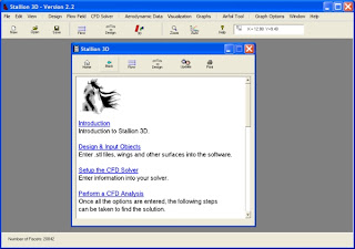 |
| Stallion 3D Main Window |
To start the analysis, click on the design menu and select the Import or Edit .STL file option. This will invoke the .stl file editor show below. The editor allows you to read in files in the ASCII format and then provide a quick preview of the input. Stallion 3D can analyze files that are water-tight. If your file has holes, you might be able to repair them with the free utility called
Netfabb-Studio Basic. Netfabb studio can also convert files from a variety of formats to the .stl format.
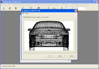 |
| A car from Turbosquid.com as seen in Stallion 3D. |
The .stl input box also allow you to rotate and translate the part. This allows you to point the leading edge of the model (longitudinal direction) along the x-axis and the lateral direction along the y-axis.
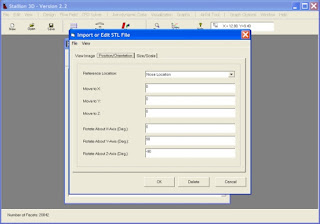 |
| The .stl dialog box can be used to orient the model. |
Before exiting the .stl import box, you can also explore the options to scale the model and set the correct dimensions. The default in Stallion 3D is meters, however, you can select inches, feet and cm.
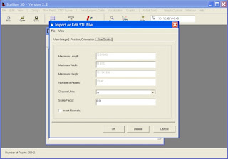 |
| Scale and dimension the solid model. |
Once the part has been imported into Stallion 3D, it can be view in wire frame mode in the Design Editor. This screen can also be used to add more components (such as wings) to the model.
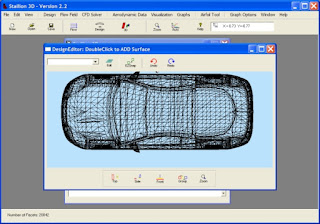 |
| The design editor window can be used to add wings and other components to the model. |
The next step is to analyze the model. Stallion 3D performs a 3-dimensional CFD analysis on an ordinary PC running MS Windows. The user can choose the model size and settings by clicking the CFD Solver menu followed by the Setup CFD option. In the first tab, the user can select the CFD problem size (number of nodes) and layout. The options are for a quick run (less accurate) or a moderately sized problem (more accurate). In this problem, I choose a Small Size ( less than 240,000) nodes.
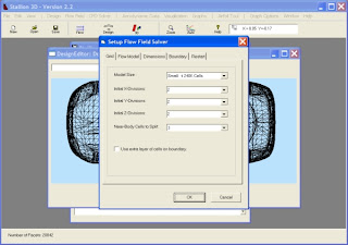 |
| The user can choose the problem size. A quick run is helpful to test the setup. |
The next option is to choose the flow domain dimensions and location. The flow domain is a big cube. I recommend that the length of the flow domain is about 10 times the maximum length of the part. This allows quicker convergence and better accuracy for the radiation boundary conditions.
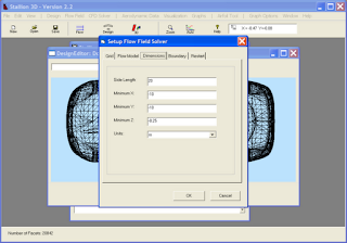 |
| Set the flow domain dimensions to simulate the physics and facilitate convergence. |
For the car problem, I select the lower z-dimension to coincide with the ground and then make the ground a reflection plane (instead of a radiating boundary). This will simulate the hard road.
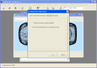 |
| Set the lower boundary as reflective (instead of radiative) to simulate the road. |
The next step in the solution is to set the flow speed and reference areas and lengths for the lift, drag and moment computations.
Finally, simply click the CFD Solver menu and select Generate Grid/Solve flow. The program will automatically generate the grid and launch the flow solver. For this specific problem, the grid generation took about 20 - 30 minutes on my laptop. The algorithm generated 132,833 nodes.
Once the grid was generated, the flow solver started to solve the 3-dimensional compressible Euler equations (with the low speed flow option). The solver computes the lift, moments and pressure drag for the 3-dimensional configuration with good accuracy. Stallion 3D can also solve the 3-D Navier-Stokes equations for the same configuration.
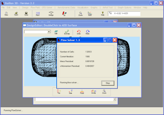 |
| The flow solver updates 132,833 nodes every iteration using a 4-stage Runge-Kutta method. |
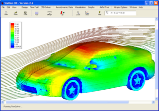
The solution converges in less than 2 hours for this problem on my laptop computer. The windows below shows the pressure computed on the surface of the car. This is obtained by clicking on the Visualization menu and selecting the View Solution option.
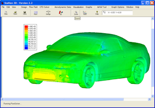 |
| Pressure on the surface of the car. |
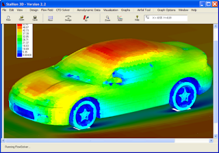
The speed near the surface of the car is a useful design parameter for drag reduction and flow visualization. Stallion 3D allows the user to see the pressure, Mach number, velocity and temperature on the surface of the part.
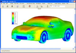 |
| Velocity on the surface of the car. |
Another technique to assess the quality of the solution is to look at the streamlines and flow at the ground plane. The following graphs show these two images.
 |
| Velocity at the ground plane. |
 |
| Flow streamlines. |
Stallion 3D computes the overall lift, drag and moments acting on the vehicle. These numbers can be used as design parameters to improve and determine the performance of the vehicle. The moments can also be used to determine stability with subsequent computations.
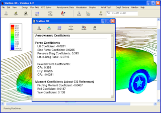 |
| Computed lift, drag and moment coefficients based on vehicle frontal area. |
Note, the .stl file must be in very good shape for good computation of the forces and moments. It must not have multiple facets (in the same location) and inverted facets. If this is the case, the user can approximate the forces on the Cartesian-front (an approximate representative of the car). This method, however, is not valid for downforce calculation. A good .stl file is required for downforce calculation when the lower boundary is used as a solid wall.
More information about Stallion 3D can be found at
http://www.hanleyinnovations.com/
Thanks for reading.


