Wednesday, November 23, 2011

Can a Turkey Escape Thanksgiving?

When in danger, it is a well known fact that turkeys can muster up very high flight speeds. Some legends have it that they can fly at supersonic speeds. 


An often overlooked fact is turkeys are extremely adept at aerodynamics and CFD analysis. They never attempt an unfamiliar regime of flight without careful analysis.

So when told about Thanksgiving, a young bird was not at all happy about its prospects.  It decided to find a way to beat the system.  "Perhaps", it thought,  "I can use my supersonic flight capabilities to escape the humans."

A quick google search revealed that humans have jet aircraft that are also capable of supersonic flight.  What are the consequences (if any) of  supersonic flight and out running a jet?

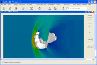
Stallion 3D Mach number analysis at M = 1.5.

Using it's laptop PC and Stallion 3D, the turkey was able to perform a careful CFD analysis within a few minutes.  A variable of concern was the temperature.

Simulation of Turkey & Jet.  Notice Temperatures....

At Mach 1.5 (a reasonable speed), the analysis showed temperatures of 466 degree K or 380 degrees Fahrenheit on most of the bird's body.


Another quick google search showed that Martha Stewart recommends that you cook your bird at 325 F.

"Hmm.... ", the turkey thought, "Can a turkey ever out run Thanksgiving?" 

"Yes!!!" exclaimed the turkey, answering its own questions, as it applied a gell-like substance (resembling cranberry sauce but with a negligibe coefficient of thermal diffusivity) to the areas indicated by red on the temeprature charts (above picture).


Happy Thanksgiving from Hanley Innovations.
http://www.hanleyinnovations.com/stallion3d.html

Friday, October 14, 2011

Analyzing "Difficult" Airfoils

Using a computer program to analyze the cross section (airfoil) of a wing, keel, sail combination or race car spoiler gives the design engineer valuable insight into the behavior and efficiency of the device.  Furthermore, airfoil analysis provides a cost effective and quick first step in the conceptual design of the product.   However, using conventional airfoil analysis tools (often based on panel methods) cannot handle a number of "difficult" shapes that are of interest to the modern design engineer.   For example, panel methods have difficulty with truncated or blunt airfoils, airfoils with gurney flaps or wicker bills (often used on high end race cars), ground effect,  thin airfoils (for modeling yacht sails) and airfoils at high angles of attack (for modeling wind energy devices).


Multi-Element wing section in ground effect computed using MultiElement Airfoils.

Computational fluid dynamics (CFD)  based on the Euler or Navier-Stokes equations provides solutions where panel methods fail.  However, even in two-dimensions, general CFD methods can prove to be costly and time-consuming due to the grid generation process for complex geometries.

MultiElement Airfoils 5.0 provides a unique solution based on Euler/Navier-Stokes equations and automatic Cartesian grid generation method.  The software is a turn-key approach to airfoils analysis (with a library of built-in airfoils and the ability to read-in DXF shapes) where solving a challenging system of multiple cross sectional shapes is as easy as analysing a single conventional airfoil.

MultiElement Airfoils is an Euler/Navier-Stokes solver based on
an automatic Cartesian grid method.

A user can enter the shape from the library of airfoils, a custom shape from a file containing the airfoil ordinates or a .dxf file.  In this case, a blunt airfoil shape is shown in the picture below.

Blunt airfoil geometry in MultiElement Airfoils.

The analysis starts by automatically generating a Cartesian grid using the program's menu system.

Automatic Cartesian grid adapts to the emersed boundary.

Next, the user can choose either an Euler equations solution or Navier-Stokes solution.  The picture below shows the Euler equations solution coupled with a boundary layer solver.  The program displays pressure, velocity ratio (seen below), Mach number, Temperature and density.

Flow velocity ratio with streamlines.

Airfoils with Gurney flaps (wicker bills) used in the racing industry can also be easily and accurately analyzed with MultiElement Airfoils 5.0.

Gurney flap grid in MultiElement Airfoils.

The Navier-Stokes solution is chosen for this analysis (the Euler solution was also obtained for comparison).  The pressure field is shown in the below picture.

Gurney flap solution showing pressure and streamlines.

The following picture shows the flow close to the gurney flap.  It features a double separation region downstream of the flap.  On the left side of the screen, a comparison is made between the surface pressure coefficient of the main airfoil and the flap computed using the Euler equations and the Navier-Stokes equations methods.

Streamlines near the trailing edge as computed in MultiElement Airfoils

Another application of MultiElement Airfoils is in analyzing thin airfoil shapes.  This is useful for the design and analysis of the propulsion system for high performance yachts and sailboats.  The picture below shows a model of the jib, mast and main sail as modeled in the software.

Sail geometry modeled in MultiElement Airfoils.

MultiElement Airfoils is ideal for computing the most optimal angles for the sail components.

Flow velocity and streamlines.

The picture below shows the mast and main sail components.  The solution suggests that the sails are not at the best angles.

Flow velocity and streamlines near the mast and main sail.

In conclusion, MultiElement Airfoils 5.0 is a modern tool for the efficient and accurate evaluation of difficult airfoil cross sections.  More information about the program can be found at http://www.hanleyinnovations.com/mefoil.html
Thursday, September 22, 2011

Transonic Airfoil Analysis for Jet Aircraft, Propellers and High Speed Blades

Introduction
Whether you design blades for propellers or airfoils for high speed executive jets, as an engineer you must have an efficient tool that is capable of screening and designing custom airfoil shapes over all speeds of operations. An aerodynamic problem that arises (and this is a potential show stopper) is the tendency of the pressure drag to increase by an order of magnitude through the transonic regime of operation. This sudden drag rise depends on such factors as airfoil thickness, camber and angle of attack.  For a propeller design, the efficiency can decrease dramatically after reaching a certain helical tip mach number (this limits forward airplane speed and/or available power).  For a wing design, the performance of the airplane can be severely limited due to airfoil shapes that were poorly designed and tested across the transonic regime of flight.  The figure below shows how the profile drag can suddenly increase on an airfoil past a given speed or Mach Number.  This Mach number is known as the drag divergence Mach number or Mdd.

Profile drag can suddenly increase by a factor of 10.

As the power of the PC increases, engineers now have access to tools to screen blades that operate poorly in the transonic regime of flight.  VisualFoil Plus has the capability to analyze airfoils in subsonic, transonic and supersonic flows. The above figure shows the pressure drag rise for a NACA 2412 airfoil as predicted using VisualFoil Plus.  The NACA 2412 is a popular airfoil for the wings of general aviation aircraft.  It is also used in some propeller designs.  Currently, propeller companies design and test propeller blades based on modern (often proprietary) airfoil shapes. 

 VisualFoil Plus can be used to design an airfoil that pushes the drag rise towards the right side of the graph resulting in a significant performance boost.  The software features automatic grid generation, a built-in airfoil library and tools to run the analysis from an external program (to facilitate custom airfoil design and analysis).


Transonic Flow Past an Airfoil.

To find out more about testing airfoils in high speed, please read the following article "High Speed Blade Screening" (.pdf file). 

More information about VisualFoil Plus can be found at http://www.hanleyinnovations.com/air_16.html.

Thursday, June 23, 2011

Designed to Start: Developing Successful Vertical Axis Wind Turbines

Small vertical axis wind turbines (VAWT) are very attractive sources of clean wind energy for individual residences, small communities, localized power supplies (such as cell phone towers) and other applications.  A major problem for custom designed and production vertical axis turbines is in starting the rotation process.  This is especially true for low wind conditions .  This blog entry provides a new solution where the designer can develop working designs directly on their personal computer and reduce both the cost of building prototypes and development times.  This results in a less expensive line of products that will be an affordable source of clean energy for a growing client base.

The Design Process
Wind turbines and other devices are efficiently designed using a modern computer aided design (CAD) program such as SolidWorks or Autodesk Inventor.  However, for the engineer to know if the designs work or not, they must be built and tested in a wind tunnel or the physical environment.  This is a time consuming and costly step. 

A faster and cost effective solution is to test the design directly on the computer (ideally the same one where the design was developed).  An aerodynamics analysis software program such as Stallion 3D that can test the turbine designs directly in their digital form (as produced by the CAD program).

The figure below shows a vertical axis wind turbine that was imported into Stallion 3D using the STL format.  This file format is available export option in most three dimensional CAD software tools.


Analyze the Turbine
The next step is to determine whether or not the design will spin under desired wind conditions.  Stallion 3D allows the engineer to enter various wind conditions and angles to test the design.  This is done by simply entering the wind condition in a dialog box as shown in the picture below.


Of course Stallion 3D is not the only software package that can perform an aerodynamics analysis on a CAD file.  However, Stallion 3D works on an ordinary personal computer or laptop that runs Windows XP, Vista or 7.  It also eliminates the time consuming and expensive process of grid generation that is inherent in other computational fluid dynamics (CFD) method.  Since cost and time reduction is the goal of this new design  process, using Stallion 3D with its automatic grid generation tool is the logical choice.  The picture below shows the pressure solution and a crosssection of the computational grid that comprises 150,000 cells.  The grid and solution for this case were obtained in less than two  hours.

Designed to Start
To design a starting machine, the engineer must test the design for various wind velocity conditions (speed and direction).   Stallion 3D computes the flow field, forces and moments for any value of the wind direction.  The picture below shows separated flow on the lower blade at 45 degree wind direction and 15 miles per hour.


The software also computes the aerodynamics moments generated by the wind turbine and compares it to the starting torque of the power generator.  If the aerodynamic moments are greater than the starting torque, then the generator will turn for the specified wind conditions and we will have success.  If not, the engineer can make modifications in the CAD program and repeat the process without the expensive step of metal cutting.  The picture below shows the forces and moment that are computed by Stallion 3D to determine the torque and structural requirements of the wind turbine tower.

Conclusion
Stallion 3D is a 3-dimensional aerodynamics software product developed by Hanley Innovations.  The product is intended as a tool for engineers, designers and students that will allow them to solve problems on their personal computers (without the need for external assistance).  It is a component of their professional toolbox and bag-of-tricks that allow them to be innovation and productive at work and contribute to their professional advancement.

More information about Stallion 3D and other professional aerodynamics software tools can be found at http://www.hanleyinnovations.com/product.html

Thursday, May 12, 2011

Smaller, Lighter Wings???

Eagles in flight give us a hint on how to make smaller, ligher wings; shorter keels; or less intrusive wind turbine blades.   The key is the tip feathers.  I wanted to know how effective these feathers might be so I used MultiSurface Aerodynamics to perform a simple test.  The figure below shows the results of this test.


In the experiment, I tested three wings.  The first wing had an aspect ratio of 4; the second had an aspect ratio of 6; the third had an aspect ratio of 4 along with wing sails (tip feathers).  The above figure shows that the wing sails elevated the performance of the wing with an aspect ratio of 4 to that of the wing with an aspect ratio of 6.

The MultiSurface Aerodynamics analysis provides proof that taking hints from nature can improve engineering structures.

Wednesday, January 12, 2011

Adding simple geometries

Stallion 3D makes it easy to analyze simple geometries such as wings, wing-bodies and bodies of revolution directly from the software.  Add a wing by specifying the airfoil shapes, the sweep and taper.  Stallion 3D allows you to choose from NACA airfoils, the UIUC airfoil database or your custom shapes.  The program automatically generates the grid, performs the computations for subsonic, transonic or supersonic flows.