Thursday, June 13, 2013

The Best Airfoil ...

Which NACA airfoil is the best? (for you?) The answer one expects is the shape with the highest lift, lowest drag and most favorable moments. 

Cl vs. Cd for 3 NACA airfoil shapes.
  
The graph above (lift vs. drag) can give us some hints.

  1. The 63-012 is good (low drag) at low lift requirements.  Perfect for a high performance keel (perhaps low aspect ratio).
  2.  The 0012 is good (low drag) at higher lift than the 63-012.  This would work well for a higher aspect ratio keel or rudder.
  3. The 23012 is good for a wing or hydrofoil. It also had good moment characteristics (not shown on graph).
Still thinking about how to choose the best airfoil shape for your design, please see the following video:


If you have questions about the performance of NACA airfoils and you need to get the coordinates or .DXF file for your designs, then I recommend the VisualFoil NACA software for Windows XP, 7 and 8. 

Thanks for reading.

Some Assembly... (I mean) .. CFD Required .....

If you are in the market for furniture and see the words "some assembly required" things can get a bit scary.  They are even more petrifying when your starting point is at the Home Depot lumber department. The same can be true for computational fluid dynamics a.k.a. CFD, math, fluid dynamics, "rocket science". 

If you are designing an airplane, CFD can be a tremendous help and time-saving tool.  However, if it takes you months to learn, weeks to grid a respectable geometry and produces "fuzzy math" as the solutions then you will not "save time and money".

Luckily the phrase "some assembly required" often means that your only tool is a screw-driver. If you have teenagers, it means that your only task is just to buy the bookshelf.

The same applies to Stallion 3D,  our easy-to-use vertical analysis tool for external aerodynamics. 

To analyze your airplane design, simply import your 3D CAD model into the program:

Step 1. Import CAD drawing of
Cessna from openVSP.

Next, the difficult part ("some CFD required") is to choose the grid size. Small for quick exploratory analysis and large to check your solutions.

Step 2.  Choose a grid size

The next step is to test how well your design performs at specific flight conditions.  You enter speed, angle of attack and side-slip angles.

Step 3.  Enter speed, angle of attack and sideslip.

Like your teenager, Stallion 3D will do all the assembly work for you.  It will automatically generate the grid and analyze the flow field.

Step 4.  Simply click the generate grid/solve flow menu.

After a few hours (depending on the computer/laptop speed and grid size), you can see the results in meaningful numbers (lift, drag, moments or the coefficients).

Step 5. Look at the results and assess the performance of your design.

The idea here is that Stallion 3D is an aerodynamics software that uses powerful built-in CFD tools.  Designers and engineers use the software to analyze concepts and choose the most promising to move forward in the project.

More information about Stallion 3D can be found at http://www.hanleyinnovations.com.

Do not hesitate to email or telephone us at (352) 240-3658 if you have questions.

Thanks for reading.

Sunday, May 26, 2013

Aerospace Capstone Design Projects Should not Stop at Slow

Years ago, I completed my bachelor's degree in aerospace engineering.  Back then, the fastest computers that I had ready access to was my Commodore 64 and of course my HP-4-CV. I used my C64 to work on a rocket staging assignment for in my senior year.  I wrote a partial differential solution (heat equation) for the CV.

NASA BWB Concept at v=290 m/s. Stl file from NASA OpenVSP.

Today, personal computers, laptops and even phones are extremely fast.  However, engineering student are forced to limit exciting design projects such as passenger jets and  futuristic supersonic transports to the conceptual design phase of subsonic flight.  The main reason for this is that current analysis tools such as CFD software can take too long for students to master over one or two semesters when faced with additional obligations such as non-engineering courses, part time jobs and other graduation requirements.

Aerospace engineering should be fun (because it is).  A quick and easy tool can help students design and analyze (on their own) race cars, jets, UAVs, and other vehicles.  It can help them to determine how delta wings of various shapes work at different angles of attack and even at supersonic speeds.

AR=2,  100 m/s at 25 deg. angle of attack (pressure).

AR=1, 100 m/s at 25 deg. angle of attack (pressure).

AR 2, 670 m/s, 25 deg angle of attack (pressure).

Over the last few years, we developed a few computer programs to help students get more out of their design projects.  The latest of these programs is Stallion 3D.

Even with time constraints, students can use their personal computers to take designs to the next speed. Using Stallion 3D, it only takes about one minute to setup a jet for analysis on a laptop computer.


The analysis can be completed (about 6 hours for 500K cells) while they use their computer for other assignments or get valuable sleep.

Stallion 3D works well with other tools available to the student (suchs as NASA's OpenVSP).   The following video shows how the two can work together.


The whole idea of Stallion 3D is to accelerate aerospace engineering education to any speed or at least to move as fast as a cow.

Cow in ground effect at M=1.6

Cow with store (M=1.6)

More information can be obtained from http://www.hanleyinnovations.com
For additional results, visit (Like) our Facebook page at https://www.facebook.com/hanleyinnovations.

Thanks for reading.

Sunday, January 13, 2013

AIAA 51st Aerospace Sciences Meeting

I would like to thank everyone who visited Hanley Innovations' booth (321) at last week's 51st AIAA Aerospace Sciences Meeting in Grapevine, Texas.


We had a great time seeing old friends and meeting new ones as we discussed the latest innovations in aerospace engineering.

I would like to remind you that Stallion 3D is now a component of the Aerodynamics ClassPack.  The ClassPack is an excellent tool for aerospace engineering education for students studying basic aerodynamics as well as students working on senior year capstone design projects. More information about the Aerodynaics ClassPack can be found at:  http://www.hanleyinnovations.com/classpack.html

The following video shows how Stallion 3D can be used with NASA vehicle Sketch Pad software.


Do not hesitate to contact us at (352) 240-3658 if you have any questions about our software products.

Thanks for reading.

Sunday, October 28, 2012

Flying Fast

One intriguing aspect a futuristic flying car is the promise of fast personal transportation. You will hover off your driveway and arrive at your destination hundreds of miles away within a few minutes. Lunch in New York and dinner in Los Angeles.

 To capitalize on this promise, the car must fly at a supersonic speeds. Supersonic flight involves shock waves (also called sonic booms) and this might not work so well for your neighbors. The following video shows a simulation of shock waves (generated using MultiElement Airfoils 5.0).


Shock waves/Sonic Boom Simulation

One way of reducing the effect of the sonic boom is to use the Busemann bi-plane concept. Of course, this arrangement of wings does not produce lift. However, they might be useful if integrated into the propulsion system or a cleverly designed shock wave deflectors for lifting surface.

 The figures below show MultiElement Airfoils calculations of the Busemann airfoil operating at on- and off-design conditions.

On-Design Analysis of Busemann bi-plane without external shock waves 
computed using MultiElement Airfoils.

Off-Design Analysis of Busemann bi-plane with external shock waves.

It is not too early to start your design of the next wave in personal transportation. Please visit http://www.hanleyinnovations.com/mefoil.html to find out more about our software for analyzing multi-element airfoils in subsonic, transonic and supersonic flows.

I look forward to your comments and questions.

Thanks for reading.   Patrick.

Monday, August 27, 2012

Why Your Next Airplane Design Will be Your Best

Why your next airplane design will be the best?  Aircraft design is an iterative process.  This is why Boeing, Airbus and even NASA need lots of scientists, engineers and mechanics to carry out the engineering process. Here's an exercise, fold a sheet of paper into a paper airplane and get it to fly to your satisfaction the very first time (how many times did it take?)

Because aircraft design is an iterative process, it becomes critical that every iteration or design step is efficient. In addition, each iteration in the design should advance the project in the right direction (this is called convergence ).  In the modern aerodynamics design, tools such as analytic methods,  computational fluid dynamics, wind tunnels, scaled models and flight testing are necessary to ensure a fast rate of convergence.

Why your next design will be the best?

1.  There are a number of airfoil analysis software currently available to help you to quickly and accurately analyze cross sectional shapes for wings, struts, rudders, landing gears, flaps and other components.  You can use  these tools to select shapes that provide good lift at the expense of low drag.  Another consideration (especially for wings) is the use of airfoils that produce high lift without huge destabilizing pitching moments (this reduces the tail drag).  Some airfoil tools are free (see Xfoil).  Other are efficient and accurate and help you to finish this crucial first iteration ahead of the pack (see, http://www.hanleyinnovations.com/vf50.html).

VisualFoil 5 can compare the performance of many airfoils on a single graph.


2.  Once you have cross sectional shapes, the next step is the skeleton airplane.  The skeleton airplane is essentially just wings, winglets, canards, flaps, tail and rudder.  The skeleton airplane should be a good enough approximation to the actual aircraft to help you to compute lift, drag, longitudinal and lateral stability, angle of trim, 3 DOF trajectories, component loading (for stress calculations) and drag reduction (winglets).

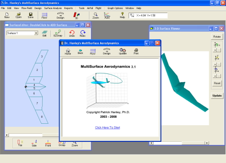
Getting the most out of the skeleton aircraft is key to the next step in the design process. Free tools such as AVL (Athena Vortex Lattice Method) allows you to analyze the skeleton aircraft using a horse-shoe vortex lattice approach.   If entering each component using a text file leaves you behind schedule, MultiSurface Aerodynamics (MSA) provides a modern user interface that expedites the design process (based on vortex rings method). MSA is the ideal tool to compute and identify form and induced drag from different wing components and design/position winglets, canards and the tail-plane (see http://www.hanleyinnovations.com/multisurface and http://pdf.aiaa.org/jaPreview/JA/2010/PVJA44453.pdf).

MultiSurface Aerodynamics can quickly perform loading & Stability Analysis

3.  As a design engineer your imagination and experience are your biggest assets. By this time in the process, you have formulated your ideas and analysis findings into a 3D solid model that resides in a CAD program (Rhino, Solid Works, Autodesk Inventor, NASA's Open Vehicle Sketch Pad openvsp.org).  This is the stage where efficiency is most critical because you must test the design as a unit. A good way to proceed is to use computational fluid dynamics or CFD methods. Traditional CFD methods requires that you construct a mesh for each design iteration that you wish to test.  This is often difficult and time consuming especially for 3D models (see http://www.symscape.com/blog/why-is-cfd-difficult).

The more parameters you can test, the better the design. If your next design is to be your best, you will benefit from Stallion 3D, a novel and accurate tool that eliminate the mesh generation process. This allows you to efficiently analyze and optimize your CAD models for this final step in the aerodynamics conceptual design process. The following video shows all the steps required to enter and analyze your aircraft design in Stallion 3D.
 
Stallion 3D can go from solid model to results in as little as 1.5 hours on a laptop computer.

More information about Stallion 3D can be found at http://www.hanleyinnovations.com/stallion3d.html.


Thanks for reading.

Friday, August 24, 2012

NASA's OpenVSP Hangar

NASA Open Vehicle Sketch Pad now has a hangar area with many 3-D models that you can use for inspiration and guides for your own original designs.  The url is: http://hangar.openvsp.org/.  The hangar currently lists 74 models for download.

 I used Stallion 3D to analyze some of the models in the hangar.  Simply export the model from  Open Vehicle Sketch Pad in the .stl format and Stallion 3D can read in and analyze the geometry.  The software can  model subsonic, transonic and supersonic external flow fields.  More information can be found at http://www.hanleyinnovations.com/stallion3d.html.
The following are some pictures from Stallion 3D.

Surface pressure on the surface of the F5 model at a speed of 290 m/s.

Velocity near the surface of the Q2-Model at V=100 mph.

Pseudo-Top-Gun Scene using the F15 for the F14 and the F5 standing in as the MIG. The airplanes were analyzed at a speed of 290 m/s.

Hypersonic waverider model at mach number of 6 (surface Mach number)

Surface pressure for the waverider model at M=6

More information about NASA's Open Vehicle Sketch Pad can be found at http://www.openvsp.org.
More information about Stallion 3D can be found at http://www.hanleyinnovations.com/stallion3d.html

Thanks for reading.