Thursday, September 25, 2025

CFD and Aerodynamics of a Blown Wing for eSTOL, STOL & eVTOL Aircraft Design and Analysis


This guide condenses the video transcript into a short, actionable tutorial. Follow the steps below to replicate the workflow shown in the video.  Applications include eSTOL, STOL and eVTOL aircraft.

Tutorial Steps (from Transcript)
  1. Hello and welcome to Hanley Innovations. Today we will outline how to set up actuator discs in Stallion 3D to implement a blown wing concept.
  2. First, we create the wing in Stallion 3D using the built-in geometry tools. This wing has a span dimension of 4 m and a cord of 1 meter.
  3. It uses a NACA 4412 from the built-in library. Next, we enter the actuator discs parameters.
  4. For all four, we set a force of 500 Newtons. We copy the first disc and set the Y center to minus 0.75.
  5. Next, with the same copy, paste a discs with Y centers of 0.25 and minus0.25 respectively to complete the propulsion distribution. Next, set up the CFD using 1 million cubes with the initial X, Y, and Z settings of 2, 2 and two.
  6. Use the default Navier Stokes solver. Then click the generate grid solve flow menu.
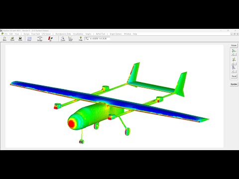
  7. Stallion 3D will automatically generate the grid and solve the flow. The results show the effects of the disc's prop wash over the wing and in the wake.
  8. We can now compare the lift force of the unpowered wing to that of the blown wing. The unpowered wing has a lift force of 24 lb in the 20 m/s flow field.
  9. The blown wing has a lift of 70.8 lb. 
  10. Until next time, thanks for watching.

 For more information, please visit https://www.hanleyinnovations.com

Wednesday, September 10, 2025

Quick and Accurate UAV Aerodynamics Analysis using Stallion 3D

Solved by Default 🛠️ — Import • Mesh • Solve in Stallion 3D

A quick walkthrough by Dr. Patrick Hanley (Hanley Innovations)

Watch: Solved by Default — Stallion 3D

Click the image to watch the short demo on YouTube.

In this quick demo, we import a drone STL, let Stallion 3D auto‑configure the CFD boundaries and domain sizing, pick a sensible default mesh, and run the solver—going from geometry to pressure contours in minutes.

What the video covers

  1. Import geometry via Design → Import STL (ASCII or binary). Set units (e.g., meters) and position/orientation.
  2. Automatic domain & boundaries: Stallion 3D sizes the CFD box and boundary conditions from the STL—so you don’t have to hand‑tune the grid extents.
  3. Optional geometry quality check: If your STL has gaps/holes, run the quick check to mitigate issues before grid generation.
  4. CFD setup with smart defaults: choose a mesh density (Quick, Medium, Large; example shown: ~1 M cells). The default solver and domain dimensions are good starting points.
  5. Generate & solve: Start meshing and the flow solution in one click.
  6. Visualize results: View the 3D geometry and pressure distribution; add legends/units (Pascals) with the graph options.

Why this workflow is fast

  • No manual domain sizing—it’s solved by default.
  • Defaults that “just work” for early design checks.
  • Applies across subsonic, transonic, and supersonic regimes for rapid concept iteration.
Watch the short demo

Prefer reading? Reply with questions—happy to help you try this on your geometry.

© Hanley Innovations • This email is informational. Video & demo: Dr. Patrick Hanley.