One of the realities of engineering design is that many decisions are made before a detailed CFD campaign ever makes sense.
Landing gear placement, strut geometry, fairings, brackets, pylons, and similar components all introduce aerodynamic penalties. The question is usually not “what is the final answer?” but rather:
- Is configuration A better than configuration B?
- How much drag or side force did this change introduce?
- Is this direction worth pursuing further?
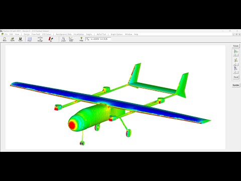
This is where Stallion 3D fits into the workflow.
Design tradeoffs without a heavy CFD process
The examples shown compare two landing gear configurations using Stallion 3D. The goal is not high-end turbulence modeling or mesh tuning. The goal is fast, consistent comparison between design options.
With Stallion 3D, design engineers can:
- Evaluate component-level tradeoffs early
- Make informed decisions without waiting on CFD specialists
- Avoid cloud compute costs and pay-per-run models
The solver and grid generation are automatic and repeatable, so changes in forces and moments reflect geometry changes, not meshing differences.
What Stallion 3D provides in this workflow
- Consistent automatic grids across multiple design variants, enabling meaningful A/B comparisons.
- Subsonic, transonic, and supersonic capability for evaluating components across a wide flight envelope.
- Designer-friendly workflow with no need to consult CFD experts for every iteration.
- Direct, interpretable outputs, such as CD_gear_2 > CD_gear_1.
- No pay-per-run cost for quick conceptual analysis.
Where this fits in the bigger picture
Stallion 3D is not intended to replace detailed CFD at later stages. Instead, it helps narrow the design space early so higher-fidelity tools are applied only when they add value.
For many projects, this reduces iteration time, cost, and dependence on limited CFD resources, while keeping decisions grounded in physics.
If you have questions about using Stallion 3D in your design process, feel free to reach out.
Learn more ➡️ https://www.hanleyinnovations.com/stallion3d.html