Cessna 210 NLF Wing: Four Models, One Story
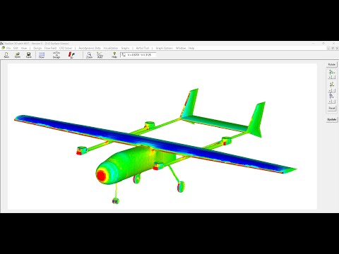
This figure shows a simple but useful comparison for a real, non-trivial configuration: a Cessna 210 modified with a NASA Natural Laminar Flow (NLF) wing. The goal here is not “pretty CFD,” but practical validation for conceptual design work.

1) Stallion 3D automatic gridding saves time on real geometries
The Cessna 210 is not an academic “wing-only” case. It has a fuselage, wing-body junctions, tail surfaces, and the usual geometric complexity that shows up immediately when you try to run a 3D analysis.
With Stallion 3D, the gridding step is not a week-long detour. Automatic Cartesian gridding makes it practical to iterate on complex shapes without turning the meshing workflow into the main project.
2) Accuracy matters: Stallion 3D validated against a NASA experiment
The comparison includes experimental results from NASA Technical Paper 2772 (full-scale general aviation airplane equipped with an advanced NLF wing). That dataset provides a grounded reference for lift and drag trends over angle of attack.
In the plots, Stallion 3D tracks the experimental behavior well over the usable range. For conceptual work, this is the point: you want predictions that are directionally correct, quantitatively reasonable, and stable enough to support decisions.
3) Vortex lattice (3DFoil) wing-tail results bracket the trends
A vortex-lattice model (via 3DFoil) is also included for the wing-tail configuration. As expected for an inviscid lifting model, it provides a fast, low-friction reference that helps “triangulate” the physics.
When the VLM curve brackets or parallels the experimental/CFD trends, it increases confidence that the configuration-level aerodynamics are being captured consistently (especially in the pre-stall regime where conceptual sizing happens).
4) Why this matters: validation for conceptual design on complex shapes
Taken together, the four views in the figure (experiment + multiple computational models) provide a practical validation set:
- Experiment: the anchor point — what actually happened in the tunnel.
- Stallion 3D: a high-utility conceptual CFD tool that can handle real geometry and produce forces and moments.
- Vortex Lattice (3DFoil): fast wing-tail estimates that add context and help bound expectations.
- Cross-comparison: agreement across models is often more useful than any single curve by itself.
This is the workflow I care about: reducing blind spots early. When multiple models (plus experimental data) tell a consistent story, you can move forward faster and spend your time on design choices instead of debating whether the analysis is “real.”
Where this approach is useful
This same validation logic applies beyond the Cessna 210 example. Once the workflow is in place, it scales naturally to:
- UAVs (wing-body-tail interactions, payload pods, booms, blended shapes)
- Light aircraft (junction flows, downwash effects, tail sizing, drag budgeting)
- Sails / marine foils (lift/drag trends, induced effects, configuration comparisons)
- General projects where geometry complexity is unavoidable and iteration speed matters
Summary
- Automatic gridding in Stallion 3D keeps complex geometry analysis practical.
- Results can be validated against experiment (here, a NASA NLF wing dataset).
- 3DFoil vortex-lattice wing-tail predictions provide a fast bracketing model.
- Multiple models + experiment = better confidence for conceptual design decisions.
If you’re doing early-stage design and want “good physics quickly” on real geometries, this is the kind of comparison that matters.
Please visit Hanley Innovations for more information ➡️ https://www.hanleyinnovations.com