Because aircraft design is an iterative process, it becomes critical that every iteration or design step is efficient. In addition, each iteration in the design should advance the project in the right direction (this is called convergence ). In the modern aerodynamics design, tools such as analytic methods, computational fluid dynamics, wind tunnels, scaled models and flight testing are necessary to ensure a fast rate of convergence.
Why your next design will be the best?
1. There are a number of airfoil analysis software currently available to help you to quickly and accurately analyze cross sectional shapes for wings, struts, rudders, landing gears, flaps and other components. You can use these tools to select shapes that provide good lift at the expense of low drag. Another consideration (especially for wings) is the use of airfoils that produce high lift without huge destabilizing pitching moments (this reduces the tail drag). Some airfoil tools are free (see Xfoil). Other are efficient and accurate and help you to finish this crucial first iteration ahead of the pack (see, http://www.hanleyinnovations.com/vf50.html).

VisualFoil 5 can compare the performance of many airfoils on a single graph.
2. Once you have cross sectional shapes, the next step is the skeleton airplane. The skeleton airplane is essentially just wings, winglets, canards, flaps, tail and rudder. The skeleton airplane should be a good enough approximation to the actual aircraft to help you to compute lift, drag, longitudinal and lateral stability, angle of trim, 3 DOF trajectories, component loading (for stress calculations) and drag reduction (winglets).
Getting the most out of the skeleton aircraft is key to the next step in the design process. Free tools such as AVL (Athena Vortex Lattice Method) allows you to analyze the skeleton aircraft using a horse-shoe vortex lattice approach. If entering each component using a text file leaves you behind schedule, MultiSurface Aerodynamics (MSA) provides a modern user interface that expedites the design process (based on vortex rings method). MSA is the ideal tool to compute and identify form and induced drag from different wing components and design/position winglets, canards and the tail-plane (see http://www.hanleyinnovations.com/multisurface and http://pdf.aiaa.org/jaPreview/JA/2010/PVJA44453.pdf).
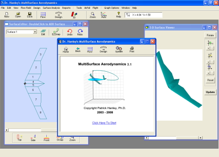
MultiSurface Aerodynamics can quickly perform loading & Stability Analysis
3. As a design engineer your imagination and experience are your biggest assets. By this time in the process, you have formulated your ideas and analysis findings into a 3D solid model that resides in a CAD program (Rhino, Solid Works, Autodesk Inventor, NASA's Open Vehicle Sketch Pad openvsp.org). This is the stage where efficiency is most critical because you must test the design as a unit. A good way to proceed is to use computational fluid dynamics or CFD methods. Traditional CFD methods requires that you construct a mesh for each design iteration that you wish to test. This is often difficult and time consuming especially for 3D models (see http://www.symscape.com/blog/why-is-cfd-difficult).
The more parameters you can test, the better the design. If your next design is to be your best, you will benefit from Stallion 3D, a novel and accurate tool that eliminate the mesh generation process. This allows you to efficiently analyze and optimize your CAD models for this final step in the aerodynamics conceptual design process. The following video shows all the steps required to enter and analyze your aircraft design in Stallion 3D.
Stallion 3D can go from solid model to results in as little as 1.5 hours on a laptop computer.
More information about Stallion 3D can be found at http://www.hanleyinnovations.com/stallion3d.html.
Thanks for reading.


